Producer information
Company:
BANK Photonics, Inc. |
| |
Address:
A747, 6335 Huqingping Road, Zhujiajiao Town, Qingpu, Shanghai, China (Mainland) Zip: 200120 |
| |
Phone:
+86-21-68869262 |
|
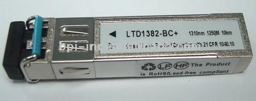
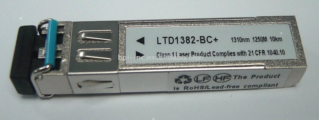
155M Single Mode SFP Transceiver
155Mbps SM SFP transceiver (20km)Features:1) Single power supply: 3.3V2) Small form factor pluggable (SFP) MSA compatible3) LVPECL compatible signal interface4) Duplex LC connectorApplications:1) ATM switches and routers2) SONET/SDH switches infrastructure3) Fast Ethernet applicationAbsolute maximum ratings:Operating conditions:Transmitter: T=0 to+70°C, Vcc=3.13~3.47VReceiver: T=0 to + 70°C, Vcc=3.13~3.47V (+3.3V)Block diagram of transceiver:Pin assignment and function definitions:It is the responsibility of the system integrator to assure that no thermal, energy, or voltage hazard exists during the hot-plug-unplug sequence. It is also the responsibility of the system integrator and end-user to minimize static electricity and the probability of ESD events by careful design.SFP transceiver electrical pad layout:Pin assignment:Functions:Notes:1. TX fault is an open collector output, which should be pulled up with a 4.7K~10K resistor on the host board to a voltage between 2.0V and Vcc+0.3V. Logic 0 indicates normal operation; logic 1 indicates a laser fault. In the low state, the output will be pulled to less than 0.8V2. TX disable is an input that is used to shut down the transmitter optical output. It is pulled up within the module with a 4.7K~10K resistor. Its states are:Low (0~0.8V)Transmitter on (>0.8V,Undefined high (2.0~3.465V)Transmitter disabled openTransmitter disabled3. MOD-DEF 0, 1 and 2 are the module definition pins, should be pulled up with a 4.7K~10K resistor on the host board. The pull-up voltage shall be VccT or VccR. MOD-DEF 0 is grounded by the module to indicate that the module is present. MOD-DEF 1 is the clock line of two wire serial interfaces for serial ID. MOD-DEF 2 is the data line of two wire serial interfaces for serial ID4. LOS is an open collector output, which should be pulled up with a 4.7K~10K resistor on the host board to a voltage between 2.0V and Vcc+0.3V. Logic 0 indicates normal operation; logic 1 indicates loss of signal. In the low state, the output will be pulled to less than 0.8V5. These are the differential receiver outputs. AC coupled 100 differential lines should be terminated with 100 (differential), at the user serves6. These are the differential transmitter inputs: AC-coupled, differential lines with 100 differential terminations inside the moduleRecommended host board supply filtering network:Example SFP host board schematic SFP:Mechanical:Order Information:
 Add to Basket Add to Basket
 Web address Web address
|


 help
help Add to favorite
 Favorite products